
|
I decided that the first stage should be automating the Z axis, as this would allow me to keep using the quill to drill holes and do basic milling while the rest of the z axis was in pieces, or not working.
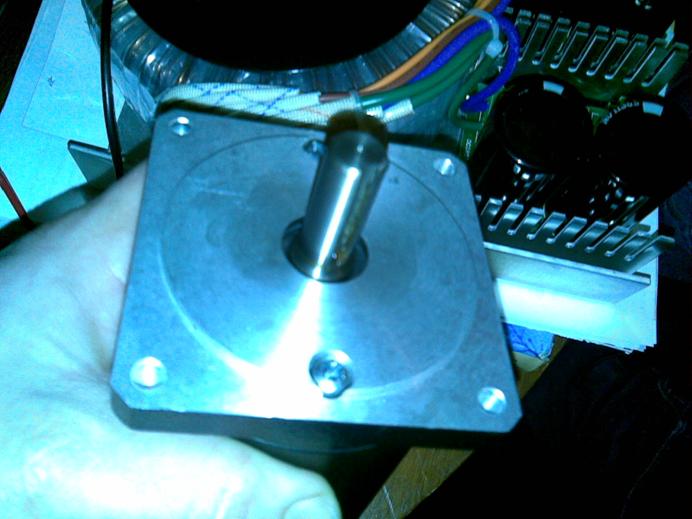
I planned to pull things apart, take measurements, reassemble the mill and then make the parts to refit. I had to develop a method to hold the NEMA34 frame motors, and transmit power from the motor to the Z lead screw. I researched the option of using a ballscrew, and after much deliberating, I chose to simply drive the crank handle with a toothed or ‘timing’ belt.
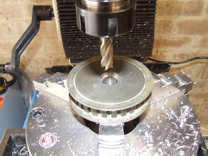
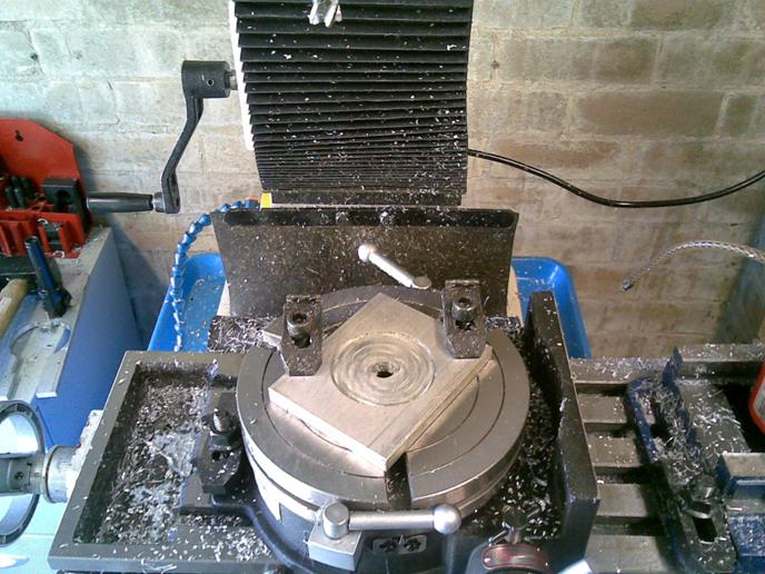
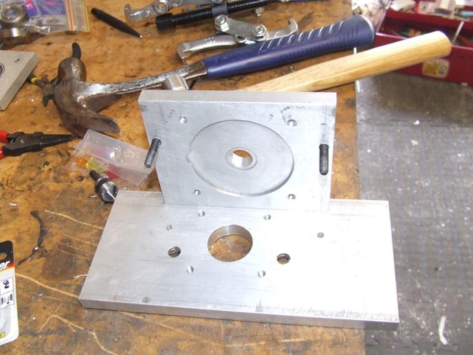
I started by measuring the motor and cutting a circular pocket for the motor boss with a rotary table, then drilled M6 holes and put heli-coils in the aluminium plate for the motor to anchor into. |
Automating the Z axis. |

|
Cutting the motor boss from 100 x 12mm Aluminium plate, 125 mm length.
|
|
Grae-Tech |
|
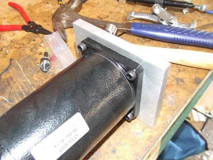
After drilling, tapping and inserting M6 heli-coils, I fixed the servo motor to the motor mounting plate. |
|
The next step was to fix another plate to the motor mount to make stand offs. I made this out of scrap that was big enough |
|
After fixing the two parts together, I added some gussets for extra strength incase the motor pulled too hard and snapped the M6 cap screws.
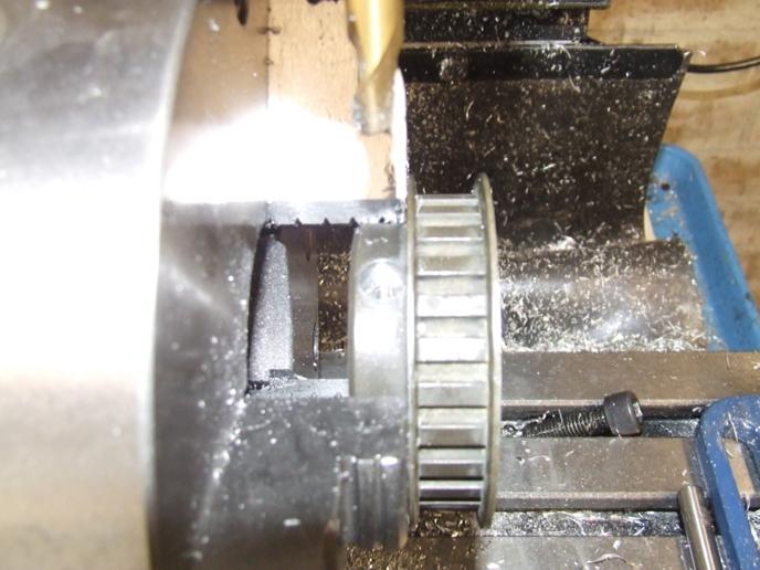
I purchased a XL10 pulley, and bored it to 1/2” and cut a 4mm keyway to suit. (Yes, that is right, an imperial size motor shaft with metric keyway!- go figure?) |

|
I purchased an XL26 pulley and bored it to 17mm to suit the Z axis shaft. I also counter-bored and tapped an M6 thread for two opposing M6 x 30 socket head cap screws, which fit perfectly to clamp the pulley to the shaft. |